
Calculating arc flash incident energy and boundary
April 22, 2021
By Terry Becker, P.Eng.
Risks should be assessed before energized work tasks are completed.
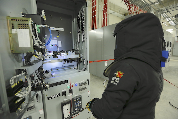
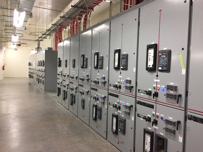
Photos courtesy Oberon Company.
Not many electrical engineers across Canada seem to be aware of Institute of Electrical and Electronics Engineers (IEEE) 1584.1, Guide for the Specification of Scope and Deliverable Requirements for An Arc-Flash Hazard Calculation Study in Accordance with IEEE Std 1584. This is unfortunate, as the guide explains steps to complete a power system study, calculate arc flash incident energy and boundary and generate a quality engineering report.
IEEE 1584.1 was first published in 2013—as a companion to IEEE 1584, Guide for Performing Arc-Flash Hazard Calculations—to ensure such incident energy analysis studies were completed correctly, with a detailed report aligned with good engineering practices. With both documents, an electrical engineer can substantiate any assumptions/parameter selections and/or disclaimers they may include in reports to their clients.
Required steps
When calculating arc flash hazard incident energy, IEEE 1584-2018 requires the following steps to be completed.
Step 1: Collect the system and installation data.
Start with an available single line diagram, use specific electrical equipment data sheets and request electrical utility fault data for each service. With this data, create a digital single line diagram model in power engineering software. Configure the ‘software arc flash module’ before starting calculations.
Step 2: Determine the system modes of operation.
This is different from strictly completing a short circuit analysis. You need to consider single mode or multiple modes when determining both low (minimum) and high (maximum) bolted fault currents. For motor contributions less than or equal to 50 hp—and in some cases with client requirements for motors less than 200 hp—lump the motors.
Step 3: Address three-phase electrical equipment.
The guide says “sustainable arcs are possible, but less likely, in three-phase systems operating at 240 V AC nominal or less with an available short-circuit current less than 2,000 A.” For 208-V AC three-phase electrical equipment at 2,000 A, the available fault current is typically a 45-kVA or higher transformer size and all related panelboards will require calculations. Alternatively, the arc flash personal protective equipment (PPE) category method in CSA Z462, Workplace Electrical Safety, Table 6A, could be applied where the transformer is up to 300 kVA, depending on impedance. The minimum recommendation is 8.0-cal/cm2 arc thermal performance value (ATPV) arc flash PPE.
Step 4: Determine gaps for electrical equipment.
Determine typical gaps and enclosure sizes based on system voltages and classes. If you increase the gap from the default values, calculated incident energy will increase. Use typical data; no field measurements are required, unless atypical electrical equipment is identified. Verify with the manufacturer’s shop drawings, if available. The gap does affect incident energy calculations, but is not as significant as other parameters.
Step 5: Determine the box correction factor (shallow vs. typical).
Again, field measurements are not required. Use typical data. Assume the worst-case scenario for motor control centre (MCC) starter buckets or other power distribution equipment where box sizes may vary. The box correction factor does not affect incident energy results as significantly as other parameters, such as the box/electrode configuration.
Step 6: Determine the electrical equipment box/electrode configuration.
The available configurations are vertical conductors in a box (VCB), vertical conductors terminated in a barrier in a box (VCBB), horizontal conductors in a box (HCB), vertical conductors in open air (VOA) and horizontal conductors in open air (HOA). HCB yields the highest calculated incident energy, followed by VCBB, while VCB yields the lowest incident energy. In some cases, two separate box/electrode configurations—and two separate arc flash and shock equipment labels—may be required for a single piece of electrical equipment.
Typical working distances may be used unless the electrical equipment is unique.
Step 7: Determine working distance.
This is the anticipated distance from the abnormal arcing fault location in the electrical equipment to the qualified electrical worker’s (QEW’s) face and torso. Use typical working distances, unless the electrical equipment is unique. Increasing the working distance reduces incident energy. For an application where the distance can be increased in the field by the QEW, use that working distance in your calculations and document it in the report.
Step 8: Calculate arcing current.
The system grounding does not affect the incident energy calculation, as per the formulas in IEEE 1584.
Step 9: Determine the arc duration.
Use the two-second guideline if required. Adequate egress from the work task area is required and should be noted in the report.
Step 10: Calculate incident energy for each location.
Calculate the incident energy at the assumed working distance for each specific location of the electrical equipment where an energized work task may be completed. You may need two calculations for a specific piece of electrical equipment if you decide to use two box/electrode configurations relating to specific energized work tasks.
Step 11: Determine the arc flash boundary.
Determine the distance for the arc flash boundary for the electrical equipment where energized work tasks will be completed. This is the distance from the abnormal arcing fault where the incident energy is 1.2 cal/cm2, i.e. the threshold value that can ignite flammable clothing.
Step 12: Draft and issue the P.Eng.-stamped report.
IEEE 1584.1 recommends the report include the following:
- Eng.-stamped cover page.
- Executive summary.
- Scope of study and results summary.
- Background information.
- Review of system data.
- Short circuit analysis results.
- Protective device co-ordination study.
- Arc flash hazard incident energy analysis.
- Recommendations for incident energy reduction.
- Appendices for definitions, IEEE device numbers, single-line diagrams, utility fault data, field data sheets, short circuit data and analysis report, time current curves (TCCs), electrical protective device settings, arc flash results, examples of arc flash and shock equipment labels, etc.
Too many reports include misinformation, errors and omissions. With the most recent edition of IEEE 1584, it has become more important for electrical engineers to document in detail any assumptions, disclaimers and field data validation. Conservative assumptions and unnecessary field measurements can add an unreasonable cost burden for the client.
It is also extremely important for the arc flash and shock label recommendations to meet the minimum requirements in CSA Z462. The ‘danger’ signal pane should only be used where calculated incident energy is greater than 140 cal/cm2. The footer of the label should identify the protective device and indicate the location of the incident energy (e.g. load side, line side or bus).
For all of these reasons, electrical engineers should purchase and review IEEE 1584 and 1584.1 in detail when analyzing, calculating and documenting arc flash incident energy and boundary distance for their clients.
Terry Becker, P.Eng., is past vice-chair of the CSA Z462 standard technical committee, voting member for the CSA Z463 (Maintenance of Electrical Systems) standard technical committee and voting member for the IEEE 1584 technical committee. He runs TW Becker Electrical Safety Consulting and can be contacted at terry.becker@twbesc.ca. This article originally appeared in the March/April 2021 issue of Canadian Consulting Engineer.