
World’s largest Ferris wheel rises in Dubai
September 9, 2021
By CCE
It's almost twice as tall as the London Eye.
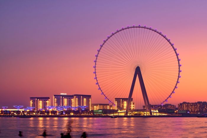
Photo courtesy Enerpac Heavy Lifting Technology.
Set to open to the public next month, the Ain Dubai is the world’s largest and tallest ‘observation wheel.’ At more than 820 ft tall, it stands above the previous global record holder, the 551-ft High Roller in Las Vegas, Nev., and is almost twice the height of England’s London Eye.
Building the structure for Bluewaters, an island attraction in Dubai, U.A.E., was a major engineering challenge, given such local factors as sandstorms, strong offshore winds, ambient temperatures up to 45 C and steel temperatures in direct sunlight reaching 80 C. Enerpac Heavy Lifting Technology of Menomee Falls, Wis., which specializes in engineering hydraulics systems, proposed a push-pull system for the Ferris wheel’s construction.
The Ain Dubai comprises a wheel rim, rotating hub and fixed spindles mounted on four support legs. The rim, 787 ft in diameter, was assembled from eight segments that were welded together and connected to the hub by cable spokes, each longer than a football field. As the height of the wheel assembly is well beyond the reach of a traditional crane, an alternative method was needed.
With the push-pull system, a pair of hydraulic grippers were set up at the base of the wheel. They were used to push the wheel forward, effectively rotating it, then released and pulled back into position using hydraulic cylinders. The push-pull operation was then repeated.
Aside from environmental conditions, the project’s constraints included rotational loads up to 2,572 tons, the largest ever handled by such a system, which had to be accommodated within limited space and ensure highly accurate control of wheel rim movement. The entire load of the partially completed wheel was borne by the push-pull system for the first six months of the project’s construction. Only once construction moved beyond the ‘12 o’clock’ point could the load be shared with the wheel’s support legs.
Following the assembly of the wheel’s support legs and the addition of the hub, each of the eight segments was added. First, they were lifted by crane onto a steep support cradle positioned between the hub support legs. The push-pull system was connected to and anchored by a tower close to the end of the left side of this cradle. Then, the hydraulics design of the system ensured the rotational loads generated by the wheel’s movement were shared equally by the supporting legs, preventing instability during construction.
The system was aligned to the rim using steel wheels. The rim was held and moved by the two gripper modules in a support frame positioned on either side at the base, similar to the arrangement of a bicycle wheel’s brake blocks. Each gripper module comprised four interconnected elements: a dynamic gripper box, push-pull cylinders, a static gripper box and static balance cylinders.
Given the high loads and size limitations for the push-pull unit, Enerpac boosted the power of the gripper boxes by supplementing the hydraulic cylinders on the rim with added steel teeth pads and 12 spring-energized clamp sets. As the rim was rotated, the clamps were released by hydraulic cylinders mounted in the gripper boxes. In the clamping position, the cylinders provided enough additional force that only the static or dynamic gripper boxes were needed to hold the wheel’s rim during rotation.
In addition to clamping and holding the segments of the wheel hydraulically, Enerpac designed the gripper modules so it would be impossible to retract the backup disk springs of the static and dynamic gripper boxes simultaneously. This was an important safety locking feature, in the event of gripper box hydraulic cylinder failure.
The wheel segments were welded together as each new segment was added. Using precision hydraulic control, the push-pull system brought the wheel rim within a few millimetres of the previous rim and held it there, to enable the two segments to be welded together. Once the weld was completed, the system progressively fed the segment through, enabling the next segment to be added.
The push-pull system was powered and operated by a central hydraulic power unit (HPU). The HPU’s diesel engine, main control panel and tank with hydraulic oil were controlled by programmable logic controller (PLC) and laptop computer. In addition to the system, Enerpac supplied the drive and control system, as it has also done for the London Eye and High Roller.
With the assembly of the Ain Dubai complete and undergoing trials, tickets are on sale for rides starting Oct. 21. With 48 passenger cabins, it will be able to carry more than 1,750 visitors at a time.