
Centre Vidéotron
October 3, 2016
By Samuel Paradis, ing, SNC-Lavalin
Quebec City’s new hockey arena and entertainment venue welcomes visitors into a grand soaring hall banked with immersive technologies. But behind the scenes, the engineering of the building structure and mechanical systems are just as extraordinary.
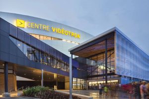
Centre Videotron, Quebec City. Photo: Stephan Groleau.
From the August-September 2016 print issue, p. 14
Following the departure of the Quebec Nordiques in 1995, the City of Quebec proposed the idea of building a multi-purpose arena to replace the aging Colisée Pepsi, which was not suitable for staging international shows or hosting teams from the National Hockey League (NHL). The proposal gained considerable public support — leading to the launch of the Videotron Centre project in late 2010.
In November 2011, the SAGP consortium, consisting of SNC-Lavalin, ABCP Architecture, GLCRM Architects and Populous, was selected to design and build the arena. All of the engineering for the project was carried out in Quebec by SNC-Lavalin.
The new building had to be capable of hosting major international sporting and entertainment events. Most importantly, it had to provide a contemporary hockey arena environment suited to serving as the home of a potential new NHL franchise.
The constraints established by the city included a $400-million budget and a July 2015 completion date. The city also wanted a building design based on sustainable development (LEED certification) and energy efficiency.
Construction was completed on schedule in July 2015. It involved many logistical challenges, with up to 480 workers on the massive site at the same time. Thanks to the dedicated efforts and close collaboration of everyone involved, the project was finished at a construction cost of $30 million below the initial $400-million budget.
The vast glass-enclosed entrance hall, over 93 metres long and 11 metres high, provides an awe-inspiring welcome for visitors arriving at the 65,037-m2 oval centre. The main building is equally majestic, with integrated open concourses and a main amphitheatre bowl on two levels that holds 18,310 seats for hockey events, and 20,500 for show events. Over 1,800 square metres of state-of-the-art video screens and over 1,000 loudspeakers surround the spectators with high-quality sound, allowing them to become totally immersed in the spectacle or sporting event they have come to see.
STRUCTURAL DESIGN
Hybrid steel and glulam structural frame
The Centre Vidéotron is a compendium of innovative ideas and technical accomplishments.
The structural frame is a hybrid of steel and glulam timber. Wood was used to support the shell of the main volume to blend with the elegant curvature of the outer envelope and give the peripheral concourse a unique appeal.
From the main concourse to the lower roof — a total height of more than 25 metres — the structure has only one point of intermediate support. The composite glulam arcs are spaced 5 metres apart, comprising the 92 facets of the entertainment area’s oval volume. Metal bridgework fills the spans between the arcs and serves as interior finishing while also supporting the envelope waterproofing and insulation. Black spruce in 25 by 25 millimetre sections was selected for its local availability and structural qualities that facilitated fine-tuning the imposing arcs.
Wood is a material that does not perform well under stress or inverse loading (as in roof trusses, for example). For this reason, steel was chosen for the Centre’s roof, some members of which have to support nearly 20,000 kN in tension. Wood was selected for the envelope columns (see 3-D model below).
The wood portion also serves to anchor the envelope’s white exterior siding panels, each of which is movable and independent. In addition to waterproofing the building and being aesthetically pleasing, the panels also function to ventilate the building laterally. Doing so required a highly complex steel-to-wood anchoring system.
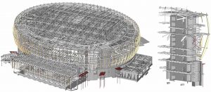
Centre Videotron, BIM structural model. SNC-Lavalin.
Reinforced concrete cages
The Videotron Centre is the first NHL-calibre arena stabilized exclusively by concrete cages (see drawing p. 16). Other NHL arenas are stiffened using conventional steel vertical wind bracing, with stairwells consisting of concrete blocks supported by the steel structure. For the Videotron Centre reinforced concrete cages were created with walls at least 400 mm thick. Lateral loads were fully taken up by the cages, which freed up a huge amount of space inside the building, since there were no vertical wind bracing members.
The next challenge was to attach the 98-m steel trusses to the concrete cages. The team decided to design steel columns into niches built into the concrete cages. By doing so it was able to transfer some of the very large horizontal loads onto the cages, thus eliminating the need for vertical wind bracing. Free spaces could therefore be more numerous and more open without affecting the stiffness of the structure. The structural system benefited the architecture and enabled the public to watch games in an open, expansive space with no visual obstructions. It can be favourably compared with the Bell Centre in Montreal, built using a different principle in 1996, where games cannot be viewed from the concourses because of the presence of the seats. Recognizing the benefits of the Videotron Centre’s structural solutions, an NHL arena in Las Vegas has taken the same approach.
MECHANICAL AND
ELECTRICAL ENGINEERING
Displacement ventilation from lower seating levels
Since the multipurpose building was intended to be a hockey arena capable of operating year round, the HVAC system, rink refrigeration system, and electrical power specifications, were crucial. What’s more, energy efficiency, as a key requirement of the project, played a central role in generating original engineering solutions.
In terms of ventilation, the quest for energy efficiency produced innovative design concepts that have never been used anywhere else in the world for buildings of this type.
The air circulation principle consists of displacement ventilation, with air being supplied at the lower seating levels rather than via air ducts located in the roof structure, which is the usual method. This approach reduced the HVAC load by treating air locally, without having to handle the entire volume of air. It also provided increased spectator comfort while ensuring optimal ice quality thanks to a locally conditioned zone above the rink surface. Acoustics were enhanced too, due to the low air velocities involved.
Cooling through the scoreboard
Implementing displacement ventilation posed a formidable challenge to the design team, who resolved it with an innovation that is the first of its kind in the world: cooling through the scoreboard. In addition to its proximity to the rink, the scoreboard has the advantage of being relatively empty inside, allowing for the insertion of ventilation ducts and air diffusers.
Using the scoreboard for air distribution enabled the creation of a cooler temperature zone for the rink, creating optimal ice quality and increasing player comfort. The main concept was to produce a dome of cool air that would create a microclimate on the ice. The system supplying the scoreboard has a 15,000-cfm flow capacity and 46-ton cooling capacity, allowing air to be supplied at temperatures as low to 8°C in this zone.
In parallel with the distribution design, conditioning the ventilation air was also critical to preserving optimal ice quality. Since maintaining the relative humidity level in the enclosure was vital to meeting these objectives, four 40,000-cfm outside air intake units with active desiccant wheels were used to supply the seats and other ventilation systems. Among other benefits, the desiccant wheels in these units keep the dew point below the ice temperature, thereby preventing surface condensation that would reduce the ice quality. The dew point of the air supplied from these units can reach levels as low as -13°C (10 grains of water per pound of dry air).
Directly fired natural gas burners are used to obtain the higher reactivation temperatures (about 139°C / 285°F) required for adequate dehumidification, with a total capacity of 8,370 pounds of water per hour. This humidity control provides superior ice quality that meets the highest standards.
Energy-efficient hydronic systems, boilers, chillers
and heat recovery
In terms of heating and cooling systems, a number of technologies and energy-efficiency measures add to the building’s overall performance. For example, practically all the hydronic system circulating pumps are fitted with variable frequency drives capable of reducing motive power during partial loads. Higher than normal temperature differentials are also employed for greater impact on pumping energy consumption — differentials of 30°F for heating and 16°F for cooling, compared to 20°F and 10°F respectively for most standard systems.
The building heating plant consists of 12 natural gas-fired, 3,000-MBH, condensation-type boilers with an efficiency of up to 97% in modulation. The boilers have stainless steel heat exchangers for enhanced durability, and there are enough of them for considerable redundancy.
High-efficiency chillers are also installed. The four chillers provide a total of over 2,330 tons of available cooling. Notable among these is an 800-ton centrifugal chiller with a variable frequency drive enabling a non-standard partial load value (NPLV) of 0.374 kW/ton. The cooling plant also has two chillers for recovering energy from interior loads and other sources to provide 5,000 MBH of heating up to 120°F. This heat is then transferred to the building low-temperature heating system, allowing offloading of two to 12 boilers. The heat comes primarily from exhaust air recovery coils, server rooms, cold storage rooms and especially from the refrigeration system, since up to 2,850 MBH of energy can be extracted from the system via a heat exchanger in heating demand periods. All the recovery results in substantial natural gas savings, thus also reducing greenhouse gases and energy costs.
For ice rink refrigeration, the system uses ammonia as the primary refrigerant. Ammonia has multiple advantages: it is 100% natural, emits no greenhouse gases, is optimally efficient and is containable at the source. The plant consists of three 150-HP, 100-TR, industrial-quality, single-screw chiller compressors, with soft start and oil coolers for energy recovery. One hundred per cent of the heat generated by these chillers can be recovered and redistributed into the building heating system, thereby limiting energy consumption.
Awards
The building has already been recognized for its innovations. It was ranked by Stadia Magazine among the top five new sports infrastructure projects of 2015. Also the Association des firmes de génie-conseil du Québec (AFG) awarded it a 2016 Grand Prix in the building structure category.
Little more than a dream a few years ago, the Videotron Centre is a remarkable engineering achievement that has become a new Quebec City landmark.
Videotron Centre Project Team
Client/Owner: Ville de Québec
Design-Builders: SAGP consortium/SNC-Lavalin, ABCP Architecture,
GLCRM Architects, Populous
Structural, mechanical SNC-Lavalin (Rémy St-Pierre, ing., André Cantin, ing.
& electrical engineers: Yves St-Georges, ing., Daniel Bourgeois, ing. Marc Leblanc)
Other key players: WSP (project management), Pomerleau
(construction management),